Smooth Motors Stepper Motor Linear Actuator: Understanding Load Capacity and Speed Ratings
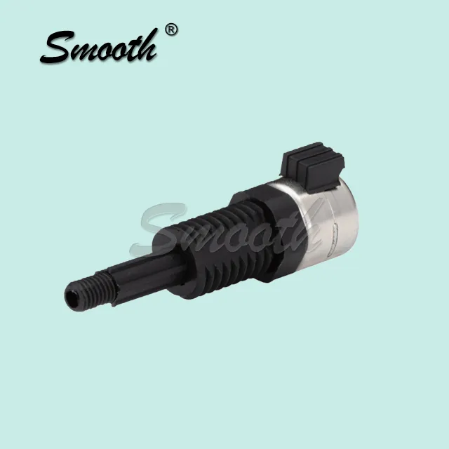
Two specifications tend to cause more confusion during actuator selection than any others: load capacity and speed rating. Understanding how they interact, rather than reading them as isolated numbers, is essential to choosing a stepper motor linear actuator that will actually perform as expected once installed in a real application. Engineers who treat these two figures as independent specifications, rather than interconnected variables on the same performance curve, often end up disappointed when a unit that looked adequate on paper struggles once it is actually put to work. Getting this balance right the first time avoids costly rework later in a project’s development cycle.
What Load Capacity Really Represents
Load capacity refers to the maximum force the actuator can move or hold reliably, but this figure often assumes ideal conditions. Real-world factors like friction, mounting angle, and acceleration forces can reduce the effective usable capacity well below the rated maximum, so engineers should never design right up against the published limit. A mounting angle that introduces additional gravitational load, for instance, can meaningfully change the effective force requirement compared to a purely horizontal application, even though the nominal weight being moved stays the same. Engineers who build in a margin for these real-world derating factors from the outset generally avoid the frustrating experience of a unit that stalls intermittently once it is actually installed in the field.
Why Speed and Load Trade Off Against Each Other
As speed increases, available torque generally decreases, which directly affects how much load the actuator can move at that higher speed. This relationship, often shown as a torque-speed curve, is one of the most important pieces of data to review, since a unit that comfortably handles a load at low speed may struggle with the same load at higher travel rates. Ignoring this relationship is one of the most common reasons a seemingly well-specified actuator underperforms once integrated into a faster-cycling machine than originally anticipated. Overlooking this relationship is a particularly common mistake among engineers new to motion control, since it is easy to assume a single torque figure applies uniformly across every operating speed.
Reading a Torque-Speed Curve Correctly
Rather than looking only at the maximum torque figure, engineers should identify the specific speed range the application will actually operate within and check the torque available at that point on the curve. This gives a far more accurate picture than relying on a single headline specification. Plotting the actual expected operating point directly onto the manufacturer’s curve, rather than estimating by eye, removes much of the guesswork from this part of the selection process. Many manufacturers also provide curves for multiple voltage or current settings, so confirming which curve corresponds to the actual driver configuration planned for the project avoids a subtle but costly misreading.
Duty Cycle’s Role in Sustained Performance
Even a stepper motor linear actuator rated for a certain load may not sustain that load indefinitely without overheating, depending on its duty cycle rating. Applications requiring near-continuous operation need to factor thermal performance into the load and speed decision, not just the mechanical torque numbers alone. A unit that performs perfectly during a short test run may behave very differently after several hours of continuous operation once internal temperatures rise closer to their rated limits. Running a representative thermal test over several hours, rather than relying purely on a manufacturer’s published duty cycle rating, gives engineers much greater confidence before committing to a final design.
Safety Margins Worth Building In
Experienced engineers typically design with a buffer beyond the calculated minimum requirement, both for load and speed, to account for wear, temperature variation, and unexpected resistance that develops over the actuator’s operational lifetime. This buffer does not need to be excessive, but even a modest safety margin can be the difference between an actuator that performs reliably for years and one that begins struggling within its first several months of continuous service. This modest buffer also provides valuable headroom if the application’s requirements evolve slightly after launch, avoiding the need for a costly component change partway through a product’s production life.
Bringing It All Together for Reliable Performance
Selecting the right unit ultimately comes down to matching real application conditions, not just catalog maximums, against the torque-speed curve and duty cycle rating together. Taking the time to verify these factors upfront prevents the frustrating scenario of an actuator that technically meets the load spec on paper but underperforms once it is actually running in the field, saving both engineering time and the cost of a mid-project redesign. Teams that document this full selection process also create a valuable reference for future projects, shortening the specification timeline considerably the next time a similar motion challenge comes up.





Post Comment